Hardware Setup
This section details how to setup and connect the BrioSens Gateway before use.
SIM Card Installation
Warning
The SIM card installation must be done in an electrostatic discharge (ESD) safe environment. Failure to do so can damage the device.
Step 1 – Remove the screw terminals cover screw using a Philips screwdriver.
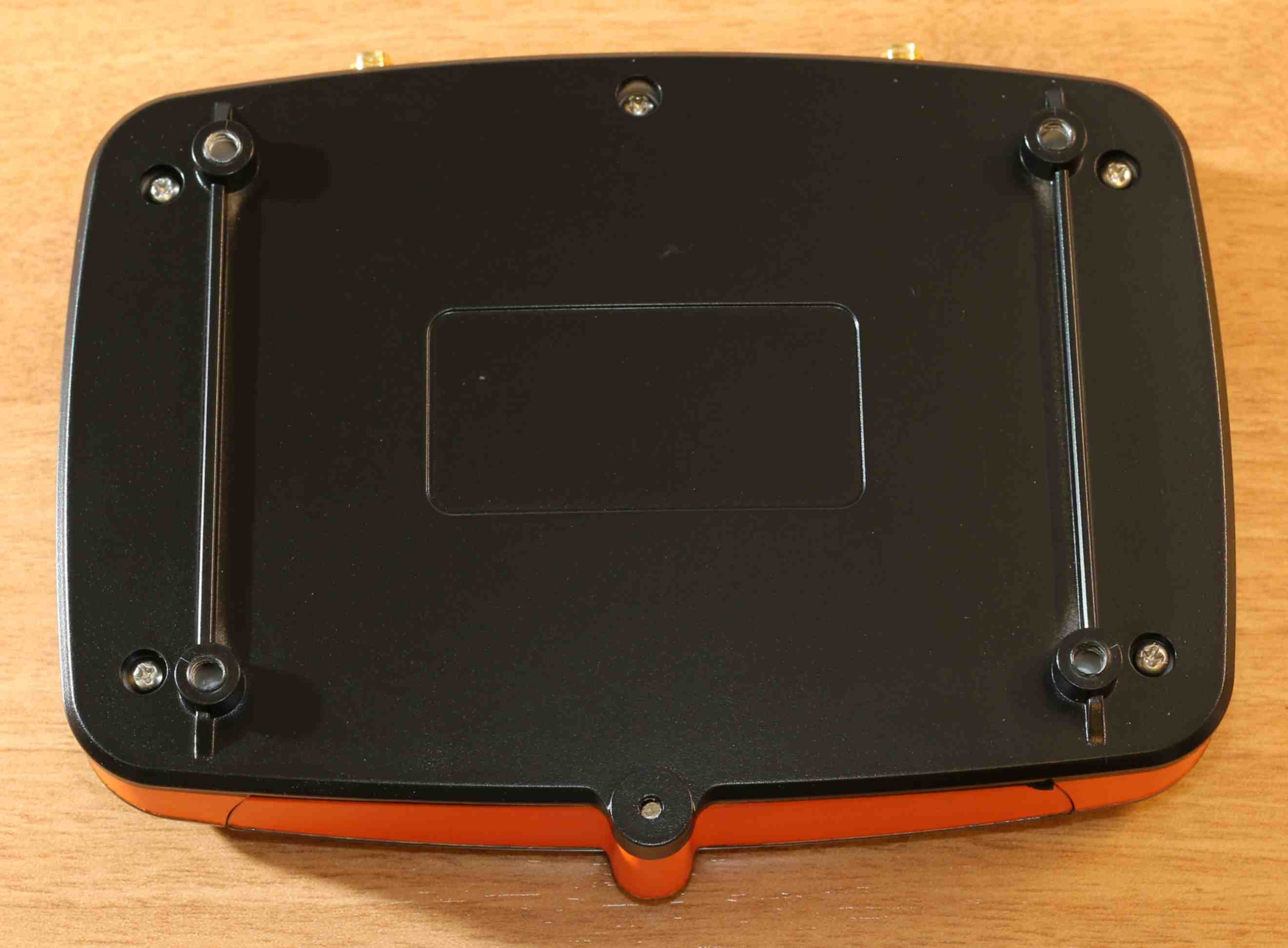
Step 2 – Flip back the unit and remove the five bottom screws using a Torx screwdriver.
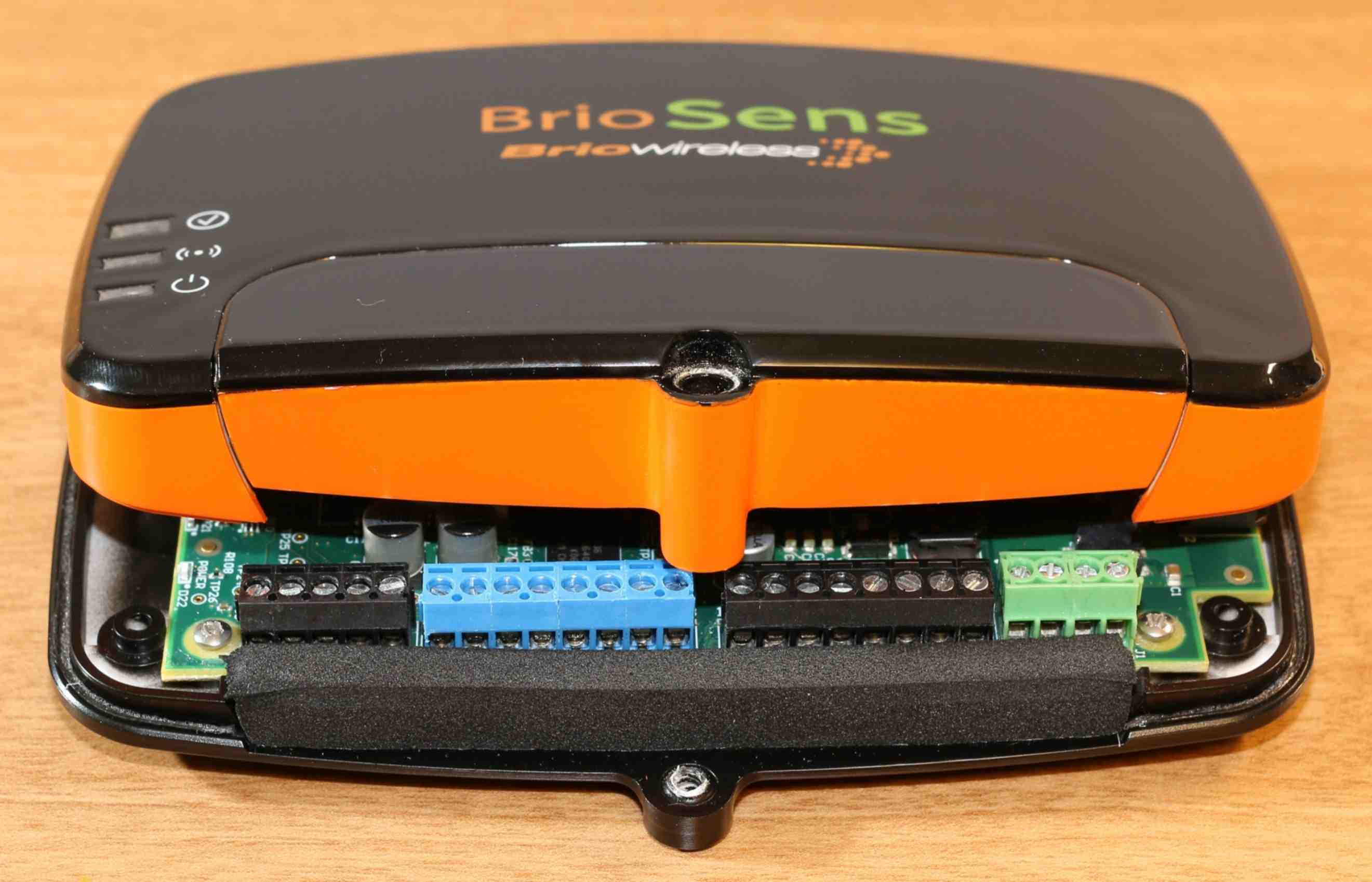
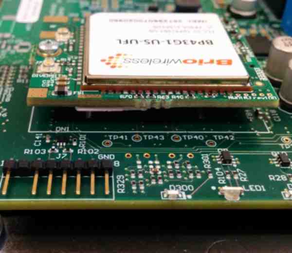
Step 3 – Flip back the device and carefully remove the top cover.
Warning
While removing the top cover, take care not to pull the coaxial cables. Excessive force may damage the coaxial cables or their mating connectors.
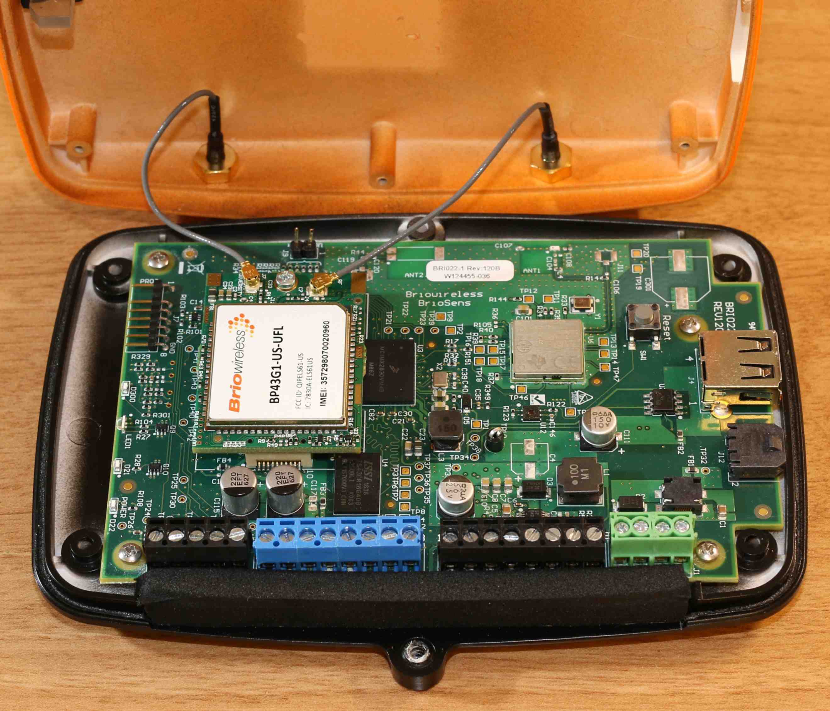
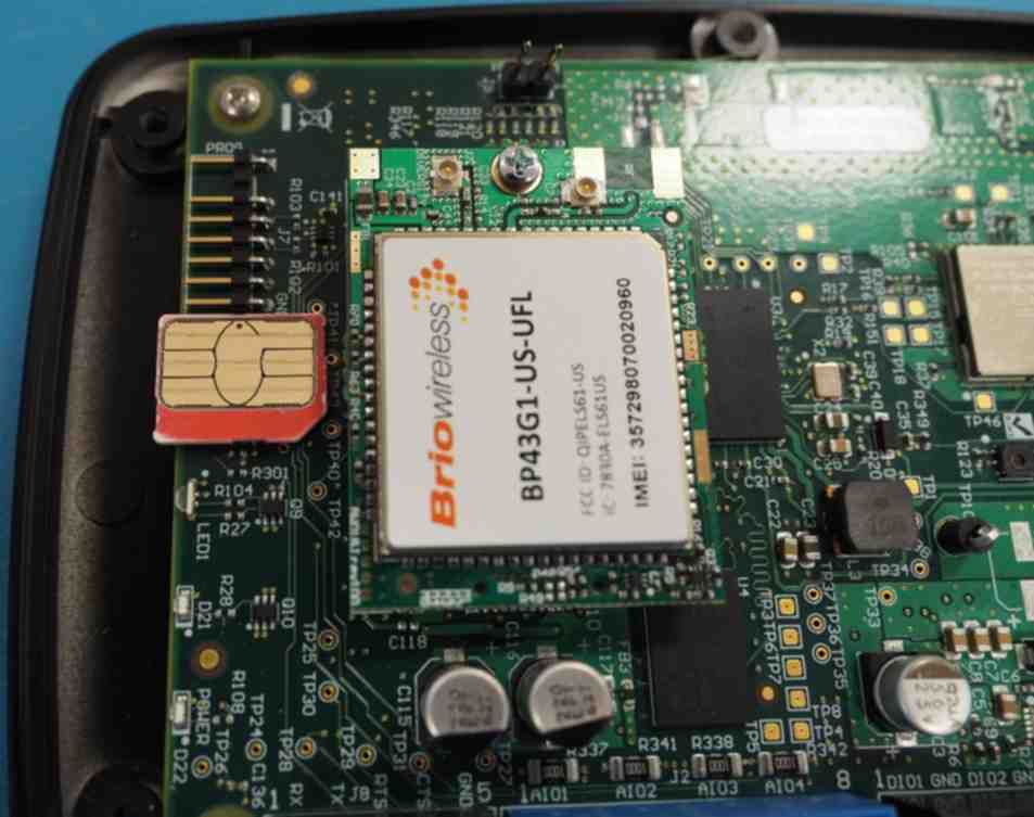
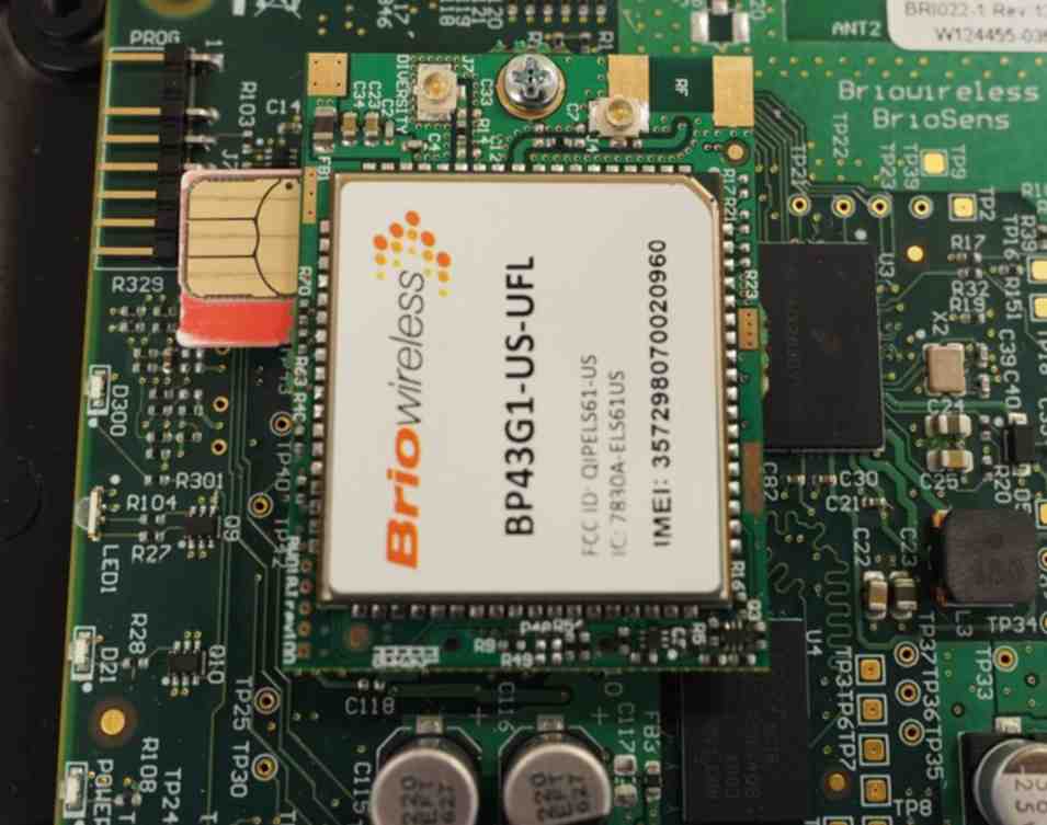
Step 4 – Insert the Micro-SIM card into the BitPipe™ SIM cardholder in the orientation shown. Press the card until it clicks-in.
Step 5 – Reinstall the top cover, the bottom five screws and the screw terminals cover screw. Do not over-tighten the screws. Stripping the screw mounts may compromise the IP65 rating on associated models.
Warning
For IP65 rated models, the gaskets must be clean to create a proper seal. Inspect the gaskets before reassembling the unit, and clean them using a lint-free cloth if necessary.
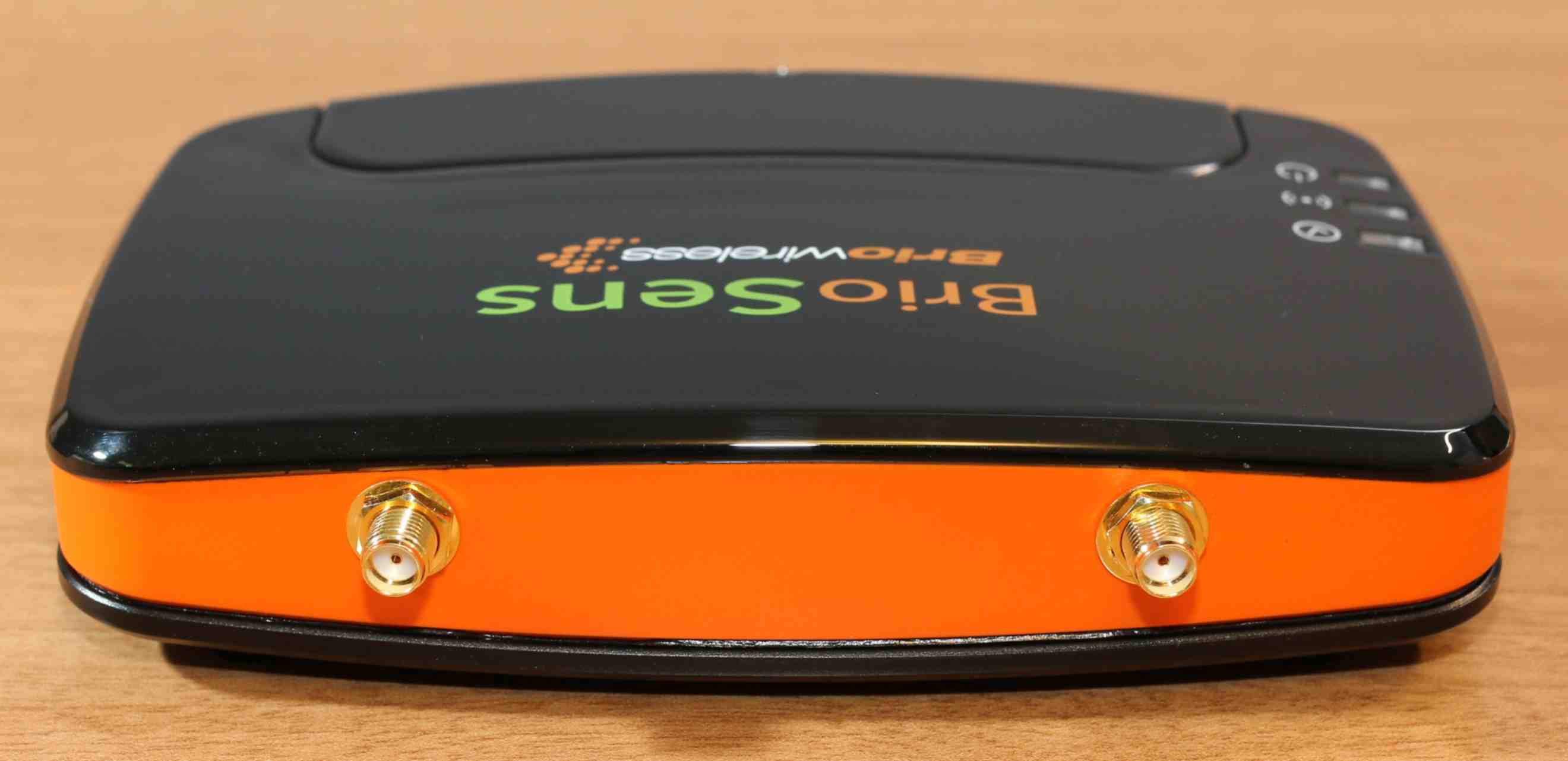
Antenna Installation (models with external antennas only)
One or two antennas (depending on the BrioSens model) must be connected to the SMA connectors located on the rear side of the unit. If needed, a high quality coaxial extension cable may be used to position the antenna(s) farther from the device. The SMA connectors have standard polarity.
Warning
The SMA connectors must be mated carefully and fastened until snug; recommended torque is 80 to 110 N·cm (7 to 10 lbf·in). Do not overtighten as this may damage the connectors and/or affect RF performances.
Below are the antenna(s) requirements:
Models with 3G (UMTS) / 2G (GSM/GPRS) cellular radio (part numbers with -32G):
-
850, 900, 1800, 1900 MHz bands for GSM/GPRS/EDGE (2G) communication
-
800, 850, 900, 1900, 2100 MHz bands for UMTS/HSPA+ (3G) communication
-
Maximum antenna gain, including cable loss, of 1.27 dBi at 850 MHz
-
Maximum antenna gain, including cable loss, of 2.51dBi at 1900 MHz
Models with 4G-LTE Cat. 1 / fallback to 3G (UMTS) cellular radio (part numbers with -43G1):
-
850, 1700/2100 (AWS), 1900 MHz bands for UMTS/HSPA+ (3G) communication
-
700, 850, 1700/2100 (AWS), 1900 MHz bands for LTE-Cat1 (4G) communication
-
Maximum antenna gain, including cable loss, of 2.15dBi at 700, 850, 1700 and 1900 MHz
Warning
Using a higher gain antenna(s) voids the user's authority to operate this equipment.
Power and Sensors Connections
Step 1 – Remove the terminals cover screw, then remove the terminals cover.
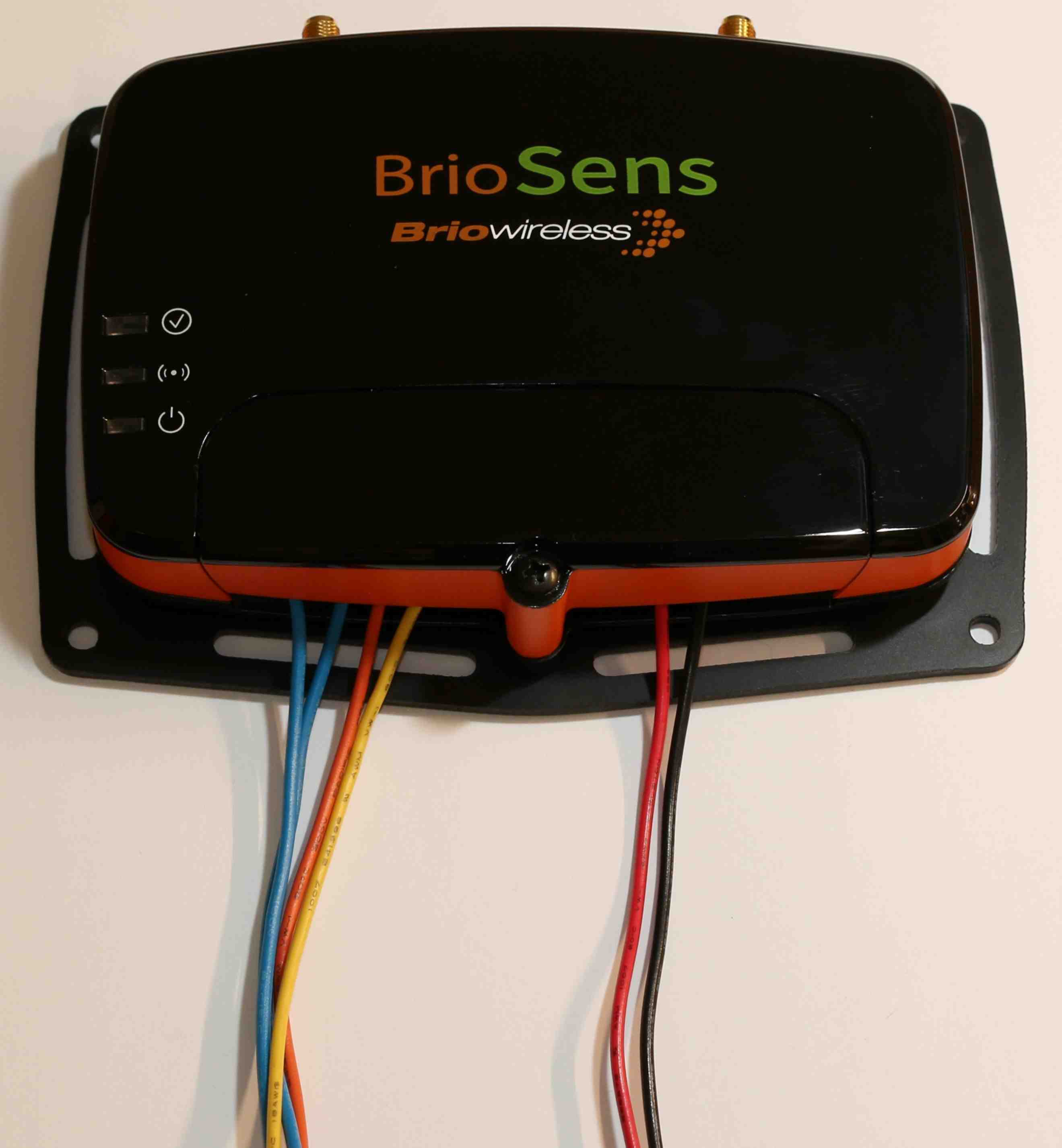
Step 2 – Connect the appropriate wires, using the pinout shown below. Secure the wires using a 2 mm flathead screwdriver. For the rating and description of each input, refer to the product specifications.
Step 3 – Reinstall the terminals cover and secure it using the terminal screw. Ensure the cover is properly aligned to ensure the IP65 Ingress Protection is maintained on associated models.
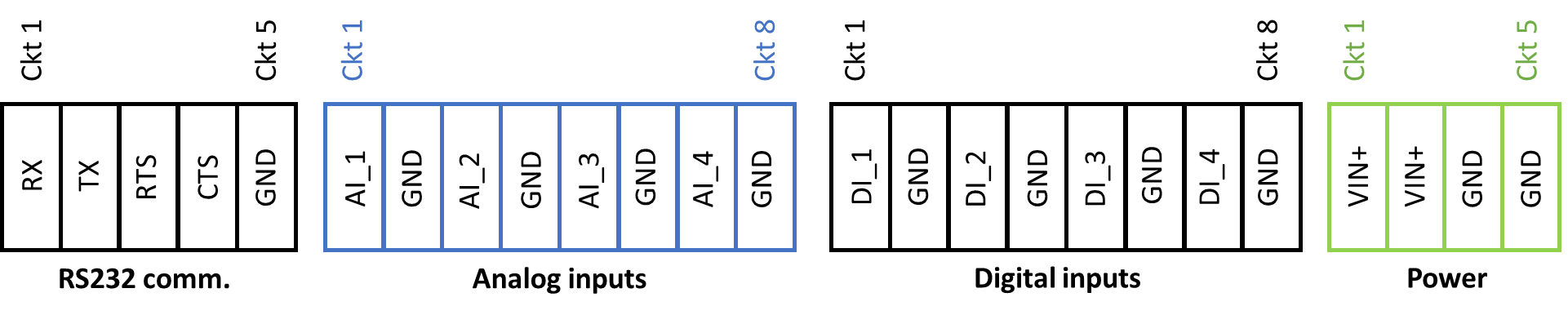
Terminal Block Pinout
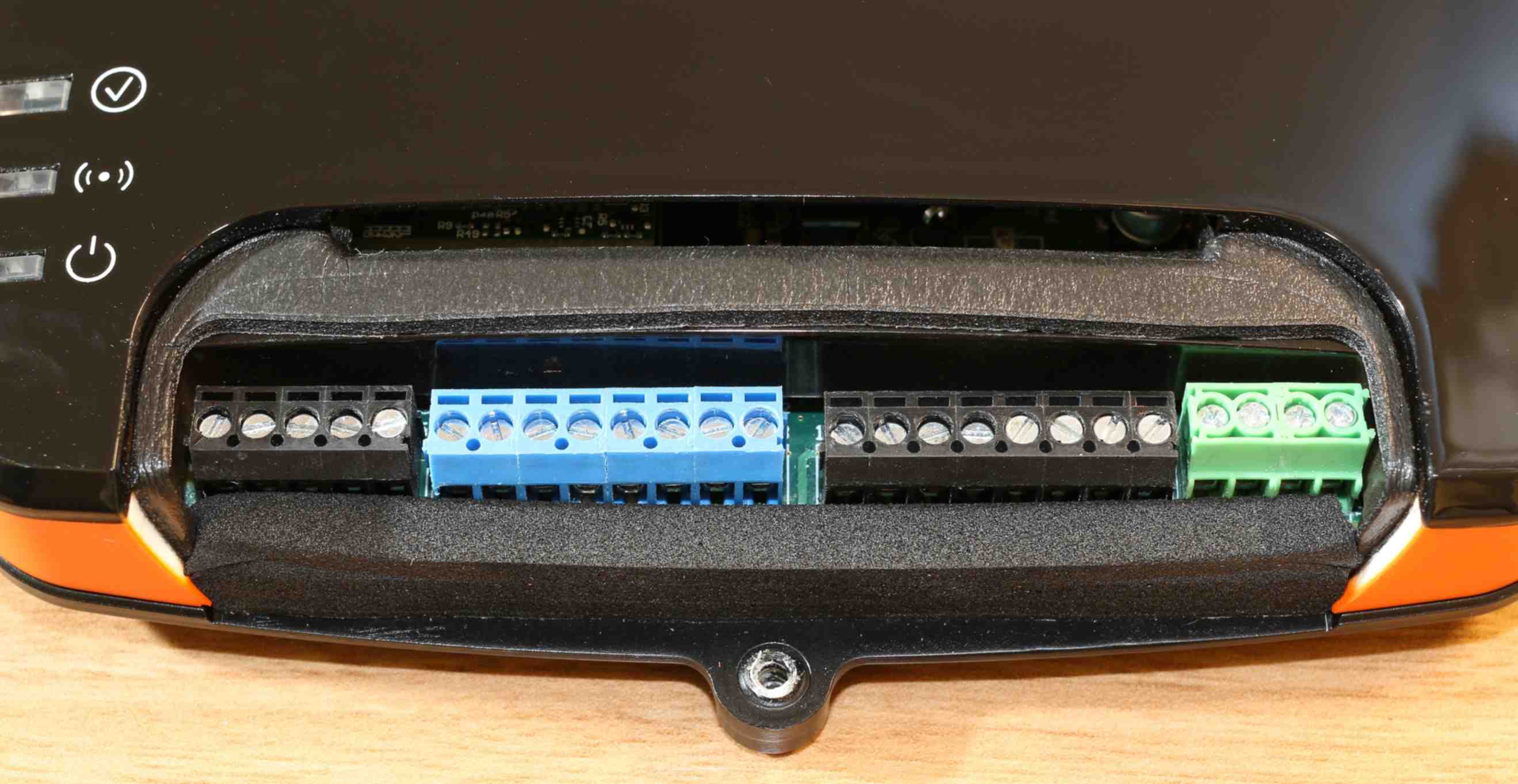
Screw Terminal Details
Wire gauge range: 16 to 26 AWG (solid or stranded wire)
Recommended torque: 20 N·cm (1.7 lbf·in)
Recommended wire strip length 5-6 mm
Side Connectors Pinout (some models only)
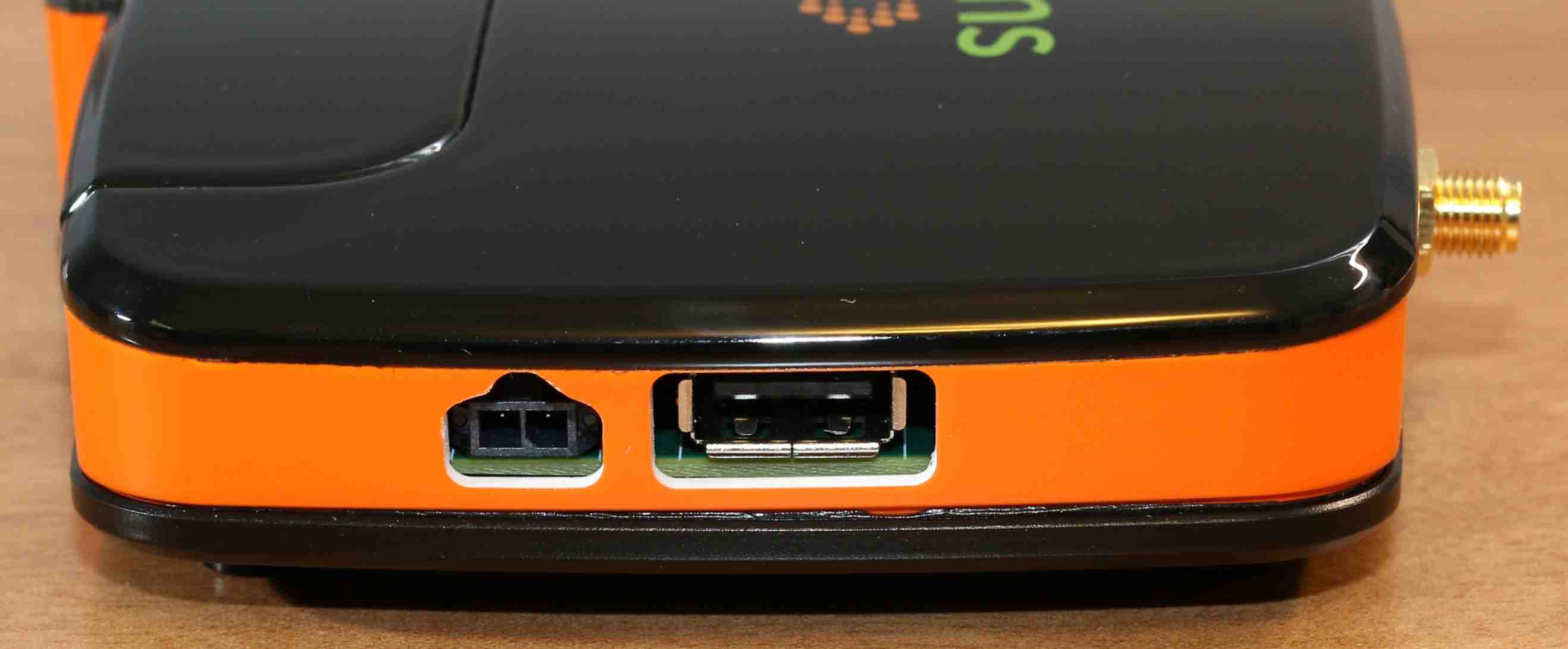


Power Connector Details
Connector model Molex 43650-0200 (tin plated contacts)
Mating connector housing: Molex 43645-0200
Recommended crimp terminal: Molex 43030-0001 (tin plated contacts)
USB Connector Details
Connector type Standard USB 2.0 type A socket
Power Connection
External DC power is typically provided to the unit using the green screw terminals. There are two VIN+ and two GND terminals. Connection is only needed on one pair; the remaining pair can be used to provide power to sensors.
Alternatively, on some models, the device can also be powered by the side power connector. Both connectors (green screw terminals and side connector) are hardwired together; therefore, when the side connector is used, the green screw terminals can be used to power sensors. In this case, the power supply will need to be sized accordingly to take into account the ucrrent required by the sensors.
Sensor Connections
BrioSens can connect to various types of analog and digital sensors. Additionally, it includes an RS-232 port for communication with sensors or other devices. Refer to the terminal block pinout above, and the specification sections for details.
Mounting Instructions
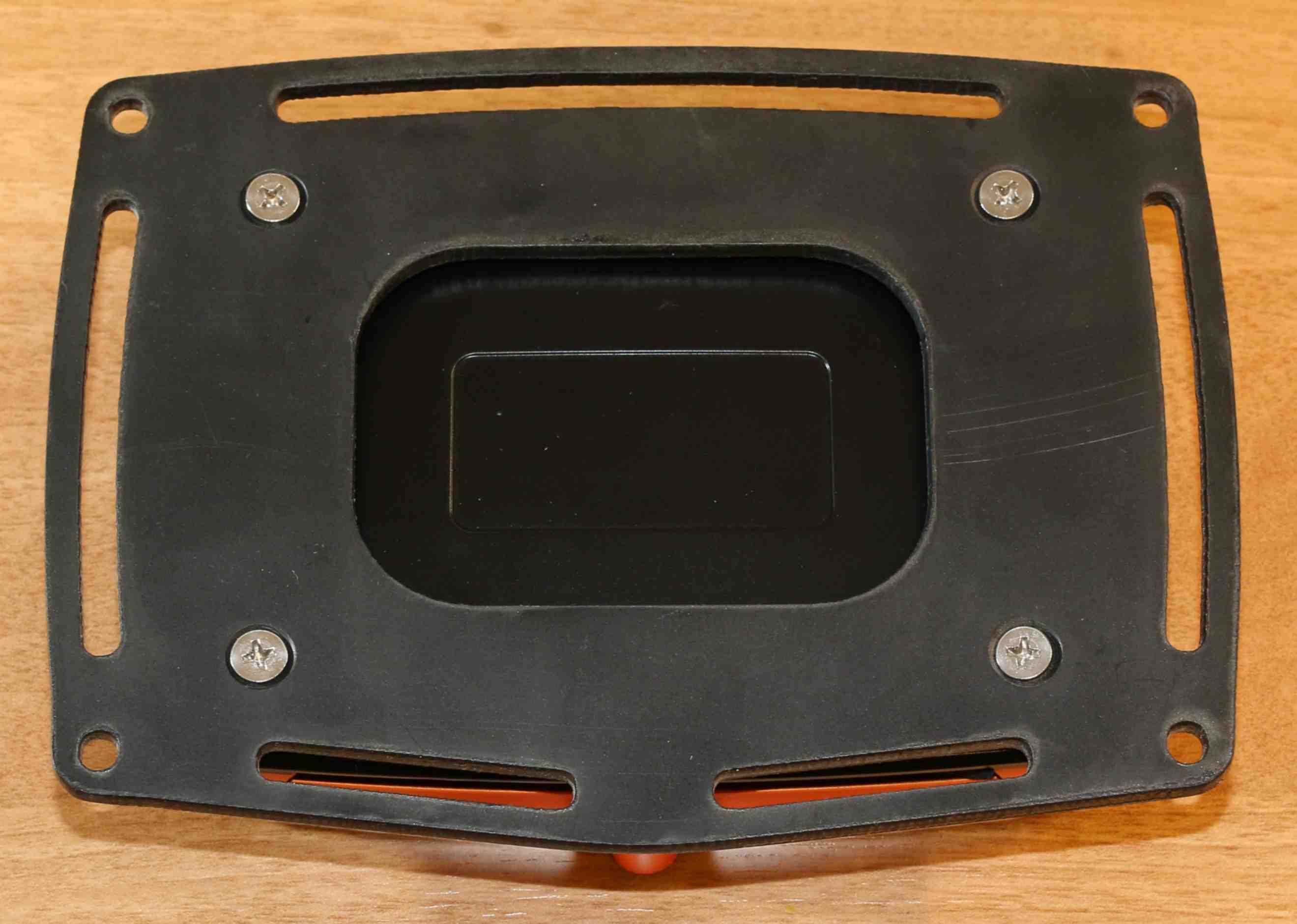
The BrioSens can be securely mounted to various surfaces using the optional mounting bracket.
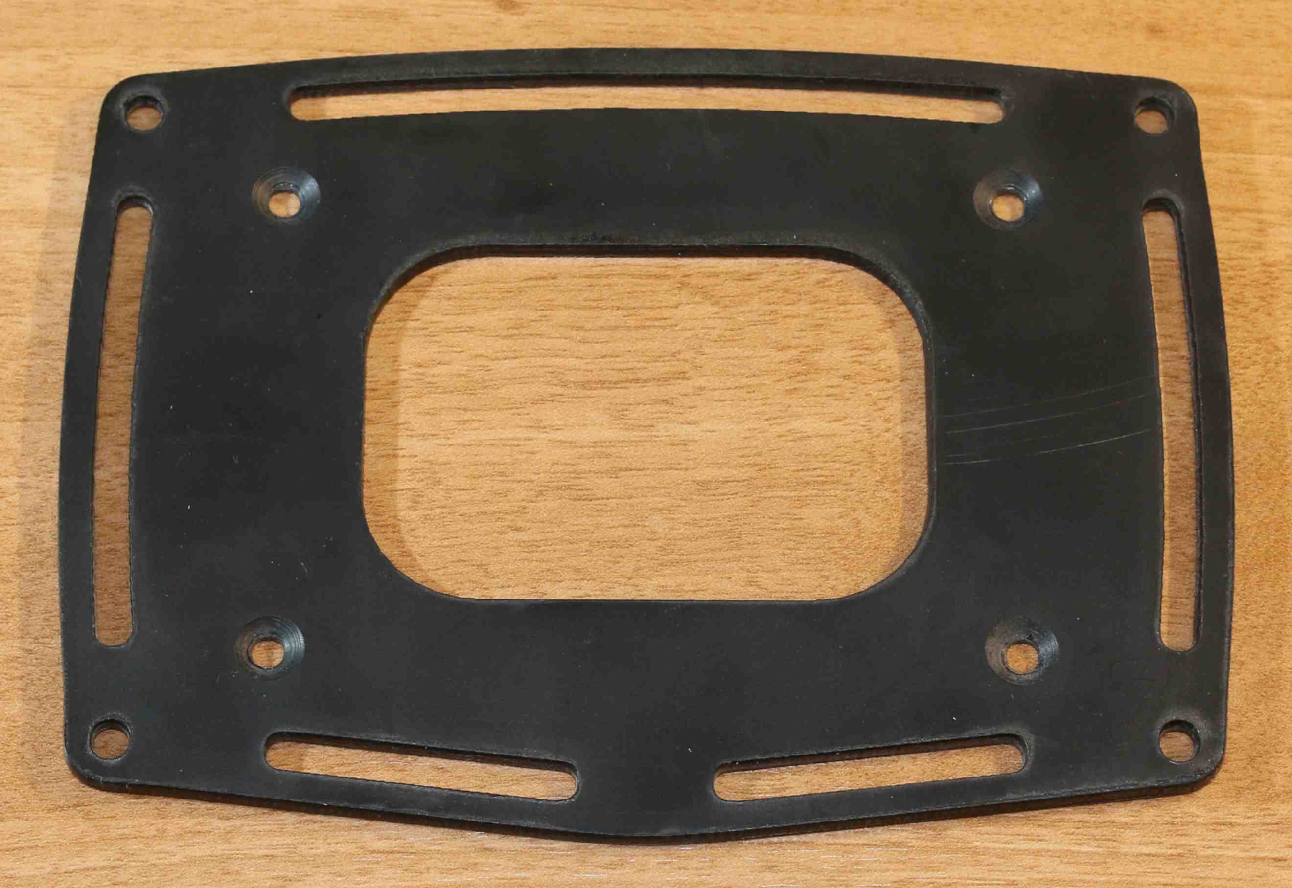
Step 1 – Remove the rubber feet to expose the mounting holes.
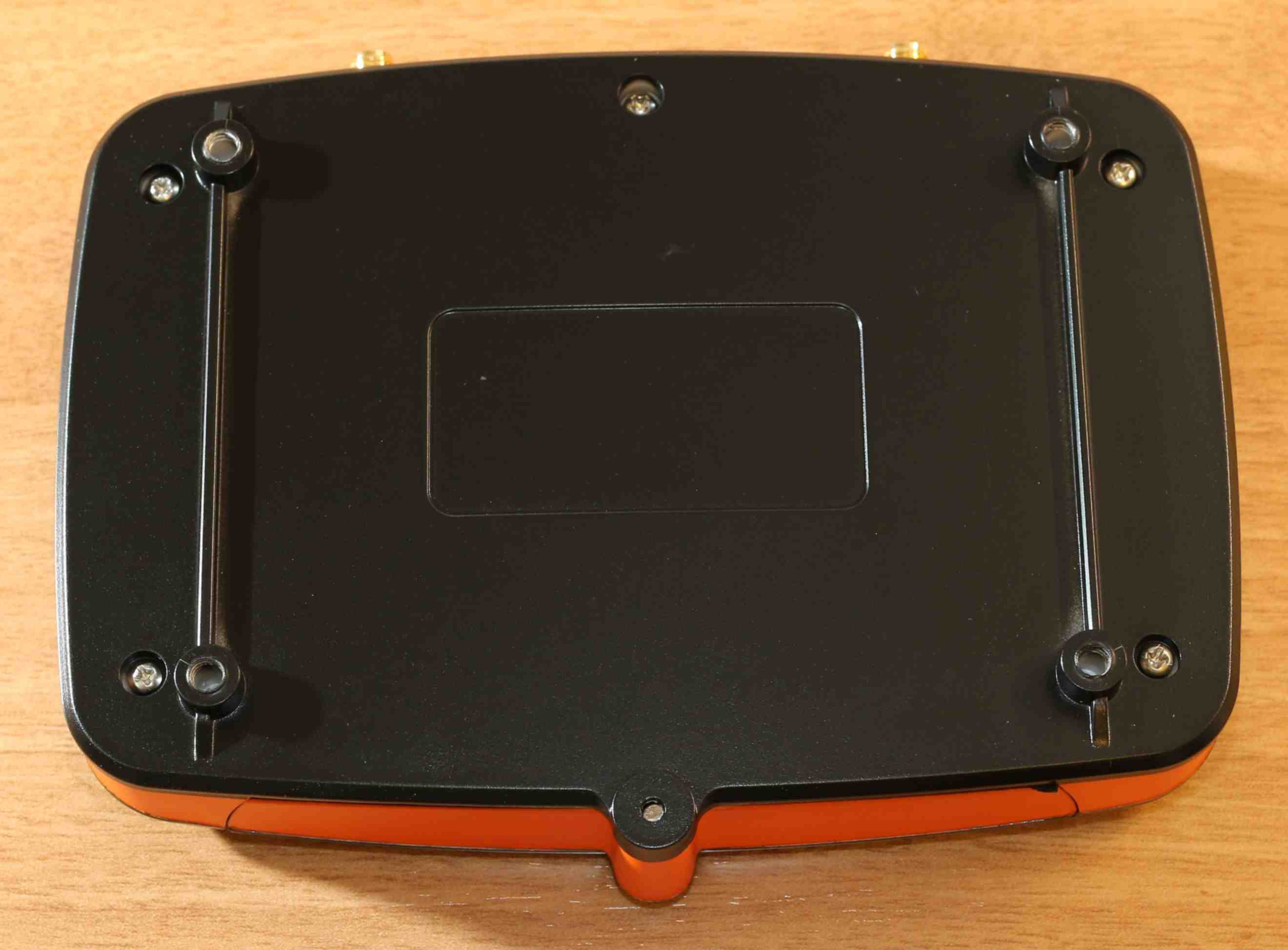
Step 2 – Align the mounting bracket with the device, and secure it using the provided screws (4 x #8-3/8 self-threading). Do not over tighten as this may strip the screw mounts.
Warning
To prevent damage to the device and/or compromise the ingress protection, only use the provided screws to secure the mounting bracket to the device.
Step 3 – Secure the mounting bracket to the desired location using any pan head, round head, or socket cap head #8 screws. Alternatively, other mounting methods can be used with side slots.
Warning
For models with IP65 ingress protection, position the device so that water on cables will flow away from wire terminals. The ideal orientation is vertical, on a wall or otherwise, with the cables extending downwards. The device must also be installed in a location protected from rain, other liquids or dusty environments.